Monday, April 17, 2017

Robo4J and the Java Flight Recorder (Laser Scanner Calibration)

The Java Flight Recorder (JFR) is a powerful feature in the Oracle JDK. It allows you to record information about the Java runtime, and the application running in the Java runtime. When designing robots, it can be an invaluable tool. Robo4J has some integration with the Java Flight Recorder out of the box.

In this blog, I will use the JFR integration to simplify the calibration necessary to make use of the LaserScanner class.

Calibrating Servos

Step one is to calibrate whatever servos are involved in doing a scan. I have a pan servo and a tilt servo. Only the pan servo is actually involved in the LaserScanner class - it provides 2D scans. That said, I need for the tilt servo to be calibrated properly too, if nothing else to ensure that I get level scans. To calibrate the servos, see my Servo Calibration blog.

First Configuration

The second step is to configure reasonable defaults for the configuration file for the LaserScannerExample ($ROBO4J_HOME/robo4j-units-rpi/src/examples/resources/lidarexample.xml). The most important part is to copy the values from your calibrated pan servo in the first step to the laserscanner.servo entry. Also, ensure that you set the minimum acquisition time depending on the version of the Lidar Lite you have. The v1 requires at least 20 ms. The v2 and later should be okay with 2ms. For the rest of the settings, leave the defaults for now.

Doing Flight Recordings

The next step is to run the a few scans using the LaserScannerExample and look at the results.
First source the envionment variables:
source scripts/rpi/environment.sh
Next run the LaserScannerExample with the flight recorder enabled. We will connect over JMX, so you need to open the appropriate ports, for example:
sudo java -XX:+UnlockCommercialFeatures -XX:+FlightRecorder -Dcom.sun.management.jmxremote.port=7091 -Dcom.sun.management.jmxremote.rmi.port=7091 -Dcom.sun.management.jmxremote.authenticate=false -Dcom.sun.management.jmxremote.ssl=false -Djava.rmi.server.hostname=coffewlan -cp $ROBO4J_PATH com.robo4j.units.rpi.lidarlite.LaserScannerExample
Next, get the robo4j-tools repo for Robo4J, and follow the instructions to start Java Mission Control (JMC) with the Robo4J plug-in.

Create a connection to your RaspberryPi running the example. You can connect with the JMX console to see that the connection works.


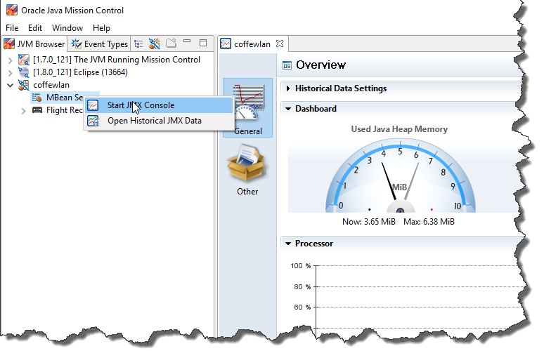
Next create a recording from Java Mission Control by right clicking on your connection and select “Start Flight Recording". You can use any recording template, just make sure to enable the Robo4J specific events in the last page of the wizard.


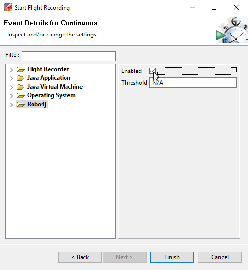
Click finish to start the recording. Once done, it will be downloaded to JMC automatically. Now, since you are using the Robo4J plug-in, the scans will be visualized for you. Open the Robo4J tab group, and select a scan to take a look at it.

If you suspect your servo is travelling too fast or slow (multiple sample points in the end with the same reading(s), weird artifacts in the end of a scan), adjust the angularSpeed. If you feel the laser do not get enough time to acquire, increase the minAcquisition time. Also, since we move the servo whilst acquiring, you may need to compensate the angular speed. Since I was lazy and didn’t have time to spend looking for a perfect physical model, there is a trim parameter to compensate (to make the left-to-right, and right-to-left scans align).

Below is a picture of a couple of individual scans on my robot without trim (simply shift- or control-click a few scans to render them simultaneously):

And the picture below is with trim set to 5.5:

Simply keep doing recordings and bisect your way to a proper trim value for your particular setup.

Summary

This blog showed that Robo4J has built in support for the Java Flight Recorder, and that the built in support is quite useful to calibrate the laser range finder (the LaserScanner class). It is also quite useful for trying out different algorithms for feature extraction and mapping using pre-existing data, but that is for another night and another blog.

Servo Calibration in Robo4J

In this blog I will show how to do simple servo calibration in Robo4J. This is, for example, important to get the laser rangefinder to work properly.

First of all we will need to configure two servo units. In our case we will use an Adafruit 16CH 12-bit PWM generator, but any RoboUnit taking a float value (normally normalized, between -1 and 1) can be used.

First sync your robo4j git repo and build everything:
git pull
./gradlew build
Next set up a classpath variable you can use. Normally just running the environment.sh script for the RaspberryPi will be fine. If not, edit the script to fit your setup.
source scripts/rpi/environment.sh
First off, copy the settings file for the calibration test. It is located in $ROBO4J_HOME/robo4j-units-rpi/src/examples/resources/calibration.xml.
For example:
cp $ROBO4J_HOME/robo4j-units-rpi/src/examples/resources/calibration.xml /tmp
Next edit the file to suit your setup. If you are about to calibrate your laser scanner, make sure that your pan servo is represented in the file. Also set all trim values to 0, and any inverted values to false. Next run the little calibration utility:
sudo java -cp $ROBO4J_PATH com.robo4j.units.rpi.pwm.CalibrationUtility /tmp/calibration.xml
You should now see something like this:

State before start:
RoboSystem state Uninitialized
================================================
  pan Initialized
  tilt Initialized

State after start:
RoboSystem state Started
================================================
  pan Started
  tilt Started


Type the servo to control and how much to move the servo, between -1 and 1. For example:
pan -1.0
Type q and enter to quit!

This is pretty self explanatory. Simply refer to the servo by name, and then set the value for it. If the servo name is “pan” in the configuration file, “pan -1.0” followed by enter will move the servo to one extreme.

For pan servos for the laser rangefinder -1 should be full left, and 1 full right. Ensure that this is the case, if not, change the inverted value for the servo configuration in the settings file. Next set the servo to 0. If the servo is off center when set to 0, carefully unscrew the servo arm without changing the position of the servo arm. Then re-attach it as close to centered as possible.

For the final tuning, use the trim value in the servo configuration to ensure that the servo is properly centered. If you are going to use the servo for panning a laser, also make note of how many degrees rotation of the arm a move from the center (0) to an extreme (-1 or 1) corresponds to.

That’s it! When you are coding/setting up your robot, simply use the settings in you calibration settings file.

Summary

This blog showed how to go about calibrating a servo in Robo4J using the very simple CalibrationUtility. This is an especially important step when the servo will be used together with the LaserScanner, something I will talk about in a future post.

Monday, April 10, 2017

5 Things I discovered about IoT at Javaland


Last month I presented the Robo4J framework at InnovationLab, during the Javaland conference (28-30.03.2017). It was really an amazing experience, not only because of the nice conference venue but also because of all the things I’ve noticed during hours of talks. Robo4J had a small stand there and it was possible to show a couple of examples live. 

The first thing I realised pretty quickly, and appreciated, was the selection of the examples I had taken with me. I packed a Lego Mindstorm Education set with Lego Sensors, Motors, RaspberryPIs with external batteries and some LCDs and sensors (all from the Adafruid company). The Lego is for kids and pretty sturdy. Adafruid provides really good quality, and is robust enough too. All has been working perfectly over the whole conference without any problems.
The second important thing was my DNS/DHCP server configured on one of my RaspberryPis, providing a stable WiFi network. It was crucial because without it none of the examples would fully work. 

The third thing I appreciated is about the interest of the people attending. Most of the people seeing all the unconnected hardware elements, laying on the table, asked about it. Maybe they didn’t believe it could work. Sure, Java and Hardware is not an easy thing; it takes some effort to make it work. I disconnected all components because I wanted to show how easy it is to build a working system by using the Robo4J framework. We then spent some time connecting all pieces together and writing some simple Robo4J applications. In the end we ran the application and it was working. My impression was that they were surprised based on the feedback I’ve received. They were impressed how easy it can be to use Java and Hardware together. 

When the people saw what Robo4J can do for IoT development it turned into a discussion about its usage. I warned everyone that Robo4J is still currently in an alpha version. Even so there are already a lot of usages where people may use Robo4J. A lot of attendees asked about how to setup the Lego Mindstorm they've bought for their kids. They never used Java there because it was not so easy to setup all together. As a consequence of those discussions we have prepared two helpful blog posts.
The fifth discovery I did is that people try hard to use RaspberryPi together with Python. All pre-prepared examples are very easy to run for the users, but than sooner or later they are struggling about how to continue with the development. I met a couple of people from Robotics startups, and they told me that they would highly appreciate to have the possibility employ Java. Aside from static typing, Java has a bigger and more active community. On the internet there are, in my opinion, much more useful libraries. Java also provides you better control over your application runtime and much more.

Summary
Javaland was extremely helpful for Robo4J. We got really nice feedback on the framework itself. There is still much work to be done before we release the first version. We are looking forward to implementing your feedback in Robo4J.


Miro, for the Robo4J Team

Monday, April 3, 2017

How to Prepare Lego EV3 for Robo4J (install leJOS)

First download the LeJOS related files:

1. Download leJOS_EV3_0.9.1-beta.tar.gz
2. Download Java for Lego Mindstorm EV3 ejdk-8-fcs-b132-linux-arm-sflt-03_mar_2014.tar.gz

Next install LeJOS on the SD card:

1. According to the manual, you should use an SD card bigger than 2GB
2. Format the SD card (on Mac you can use SDFormatter)
3. Unpack leJOS_EV3_0.9.1-beta.tar.gz
4. Go to the unpacked folder
5. Copy the lejosimage.zip file to the SD Card
6. Unpack the lejosimage.zip file
7. Move all the unpacked content to the root of the SD card
8. Copy ejdk-8-fcs-b132-linux-arm-sflt-03_mar_2014.tar.gz to the root of the SD card
9. Put the SD card back into the EV3 Lego brick
10. Start the Lego brick

We do recommend to setup WiFi on your lego Brick. Such a setup allows you to use an ssh client to connect to the brick and the scp utility to upload files. The default password is not set (any characters sequence will be accepted).

Getting Started with Robo4J

This blog post will show you how to quickly get started with Robo4J and will explain some key concepts.

Robo4J contains some key core “modules”. We will use the word “module” loosely here, as they are not quite yet JDK 9 modules. These modules are all defined as their own Gradle projects and have their own compile time dependencies expressed in Gradle.

When you build your own robot, you will normally have a dependency on the robo4j-core and the units defined for the platform you are using for your robot. For example, robo4j-units-rpi for the Raspberry Pi, or robo4j-units-lego for a Lego EV3 robot.


In this blog post I will use the provided Raspberry Pi lcd example to show how to set up and run Robo4J on the Raspberry Pi. Miro will post a Lego example later.

Module Description
robo4j-math Commonly used constructs as points, scans (for laser range scans), feature extraction and similar. Most modules depend on this module.
robo4j-hw-* A platform specific module with easy to use abstractions for a certain hardware platform. For example robo4j-hw-rpi, which contains easy to use abstraction for common off-the-shelf hardware from Adafruit and Sparkfun.
robo4j-core Defines the core high level concepts of the Robo4J framework, such as RoboContext, RoboUnit and RoboReference.
robo4j-units-* A platform specific module which defines high level RoboUnits that can be included into your projects. This modules basically ties the hardware specific module together into the Robo4J core framework, providing ready to use units that can simply be configured, either in XML or code.


Note that the robo4j-hw-* modules can be used without buying into the rest of the framework. If you simply want to bootstrap the use of the hardware you’ve purchased, without using the rest of the framework, that is certainly possible. Hopefully you will find the rest of the framework useful enough though.

First thing you want to do is to pull the robo4j core repo:
git clone https://github.com/Robo4J/robo4j.git
Once git is done pulling the source, you will want to install the modules into the local maven repository:
gradlew install
Now you are ready to pull the source for the LCD example:
git clone https://github.com/Robo4J/robo4j-rpi-lcd-example.git
We will finally build it all into a runnable fat jar:
gradlew :fatJar
Now, to run the example, simply run the jar:
java -jar build\libs\robo4j-rpi-lcd-example-alpha-0.3.jar
If you are not on a Raspberry Pi, with an Adafruit LCD shield connected to it, then you can actually run the example on any hardware, by asking the LCD factory for a Swing mockup of the Adafruit LCD:
java -Dcom.robo4j.hw.rpi.i2c.adafruitlcd.mock=true -jar build\libs\robo4j-rpi-lcd-example-alpha-0.3.jar
(This particular example can actually be run without using Robo4J core at all; see my previous post for a robo4j-hw-rpi version of the example.)

Now, let’s see how the example is actually set up. There are two example launchers for the project. One is setting up Robo4J using an XML configuration file, and one sets everything up in Java. Both are valid methods, and sometimes you may want to mix them – this is supported by the builder. I will use the XML version in this blog.

In this example there are mainly two units that we need to configure. A button unit and an LCD unit. They are both actually on the same hardware address (Adafruit uses an MCP23017 port extender to talk to both the buttons and the LCD using the same I2C address). However, it is much nicer to treat them as two logical units when wiring things up in the software, and this is exactly how Robo4J treats them.

Here is the most relevant part of the XML-file:
Note that the AdafruitLcdUnit and the AdafruitButtonUnit are provided for us, and they are simply configured for the example. Also note that they reside on the same hardware address, as expected. No code is changed or added for configuring these units. The controller unit is however ours, and it defines what should happen when a button is pressed.

The following snippet of source shows how to instantiate it all (focusing on the most relevant parts of the code):

We get ourselves a RoboBuilder, we add the configuration file as an input stream to the builder, and that’s it in terms of configuration. The builder will be used to instantiate the individual RoboUnits in the context of the overarching RoboContext. The RoboContext can be thought of as a reference to a “robot” (a collection of RoboUnits with (normally) a shared life cycle). It is currently a local reference (only in the local Java runtime), but once we get the network services up, you will also be able to look up remote RoboContexts.

Once we have the RoboContext set up, we start it, which will in turn start the individual RoboUnits. After that is done, we also provide a little start message to the LCD by getting a reference to the RoboUnit named “lcd”, and send it an initial LcdMessage.
The controller (which is not an off-the-shelf-unit) runs little demos on the LCD, and allows the user to navigate between the demos using the up and down buttons. Simply go here for the source.

I will simply note that the most important part of building a custom unit is to override the onMessage method, and that this unit is somewhat different to most units, as it is actually synchronizing on an internal state, and will skip all buttons pressed whilst a demo is running.

Summary

This was a brief introduction to what the robo4j framework currently looks like. Note that we currently have changes lined up for the core which are currently not implemented, such as changing the threading model/behaviour for individual RoboUnits using annotations. Expect things to change before we reach 1.0. Also note that we currently have a very limited amount of units implemented. This will also change before we release a 1.0. We will not release a first version of the APIs until we have implemented a few more robots in the framework.

One of the robots being migrated to Robo4J right now is Coff-E.

Hope this helps, and please note that this is all changing from day to day. Things will continue to change until, at least, after this summer. If you would like to add your own units, hardware abstractions or similar, feel free contact us at info@robo4j.io. We’d be happy to get more help!

:)

/Marcus